From time to time I hear someone’s looking to buy some audio gear or upgrade it to something better. While some are quite enthusiastic with their choice, many admit when questioned that “I know it’s not so great, but should be enough for me”. We all know that perfection is an illusion and that what’s “enough” for one may be lesser or superior to another. Good news is that we all can find that great product that matches our needs while not being something we just settle to or depleting our pockets. The tricky part is navigating through a myriad of products, “great value for the money” reviews, advertorials and questionable tests. To beat all that, you have to make a little research. One way to do it is by reading about all that stuff, comparing and then preparing your shortlist. Of course, you may find yourself thrilled from the prospect of a new buy, but that process is still tedious. Next time you’ll have also to start over maybe because you’re buying some other type of gear or two years have passed and there’s a bunch of new products on the market, replacing or competing with the older ones. The other way to do it is by learning a few basic moves, some truths and axioms, the “how it’s made”. Hopefully, this is where this guide will come into hand. I would call this a manifesto because it also declares my views; I would call it a white paper or a study but I’m neither an authority or trained on the subject. You don’t have to agree or regard my words as right and true and I encourage you to question everything you read.
Let’s start with a little demographics and for that, we do a short plunge into history. As we go further back in time, the number of gadgets decreases. We all know that Marconi played a major part in the invention of radio and while Westinghouse and General Electric started during the 1920s in USA to create household radios (revolutionized in the same years by the adoption of amplifying vacuum tubes and the discovery of AM) it took until 1970 for the household radio to reach a 95% penetration rate in US homes[1]. In 1930, the American Galvin Manufacturing Corporation marketed a Motorola branded radio receiver for cars for $130. It was expensive: the contemporary Ford Model A cost $540. In 1954, Texas Instruments, in collaboration with IDEA Corporation, announced the first commercial transistor pocket radio, the Regency TR1.

Graphic: Newspaper Advertising For The Regency TR-1 Transistor Radio, The San Bernardino County Sun, December 19, 1954
The audio gear would soon be available in smaller, more portable formats. You would find portable radios, car radios and sometimes even car vinyl players, the walkman from Sony since 1979 and so on and so forth. Nowadays, more than ever, people are listening to music on the go. Plenty of reasons could be identified for that: easy access to an audio source, longer and longer commute hours, boosting our concentration and creativity, releasing dopamine, hearing an audio book or prayers. Often, the audio source would be some streaming service from the Internet, played on the phone and listened using some earphones. Although extremely convenient, we payed a price. Portable audio gear should be light, should have an extended battery autonomy, could have some weather sealing or shock resistance and it should be… small. And here is the price we pay: we got quite accustomed that music can be heard from small devices. While yes, music can be heard from small players, there’s a trade-off in naturalness and many times in quality. Indeed, each year brings innovations into the industry, but still the laws of physics can’t be eluded. Many people will be lead to believe that some household audio device will be powerful enough just because it’s bigger than a phone or a portable player. That a one liter cabinet with a small speaker is quite powerful, big, with shocking bass response and crisp sound. Well… two liters volume looks big enough compared to our portable gadgets. Surely will do great!
I can see what you’re thinking… ok… that means what, that we all should buy some concert hall monsters? Well, not quite. But yes, you may very well prepare yourself for this ugly truth: quality audio gear, be it speakers, amplifiers or other gear, it should be heavy and many times, large. Why? Let’s take amplifiers for example. As you probably know, all audio devices including radio, television, laptops, phones etc. have an incorporated amplifier (many of them have multiple, actually). They get a signal, they have to amplify it so it can be fed as audio input to another output device or your preferred speaker or headphone. An amplifier should be ready to take as input audio signals that vary in many ways and then drive some speakers that he just met at your house that vary also in characteristics. It’s like a symphony conductor that every time has a new orchestra with new music. For a quality amplifier that is able to do that with little regard of what speakers you may have or what genre you may be listening to, with minimum distorsion and minimum influence on the sound, you would need an amplifier with a generous power transformer (could be even more than one), large and fast capacitors, powerful and well designed transistors or integrated chips with a large heatsink to dissipate the heat. All that in a good framework ready to sustain this weight. Of course, all these generous components gathered in a good electronic design. And the list does not end here. Of course, there are low power rated amplifiers in smaller sizes build with quality, but you’ll have to settle to a lower power. It may be that your listening space is small, your speakers are highly efficient and your music genre doesn’t have abrupt volume changes during the play. Then a low power amplifier may suit you. Still, low power should again not mean lousy components, just they may be smaller. We’ll come back at amplifiers later… our symphony conductors are very important.
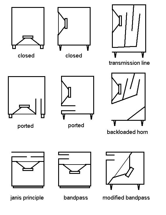
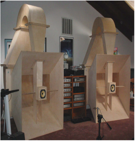
Now, getting back to the ugly truth… why do the speakers also need to be large? Well, not the tweeters need to be large. Neither the medium frequency drivers. You guessed, the problem is from the bass drivers. And I’ll add one more… it’s the cabinet also that’s of major importance (how it’s designed for the characteristics of the speakers and how it’s actually built). Not only larger speakers may need large cabinets but also small speakers may need large cabinets due to the design (ex. acoustic transmission lines, folded horns), many times trying to compensate by raising the efficiency of a rather small driver.
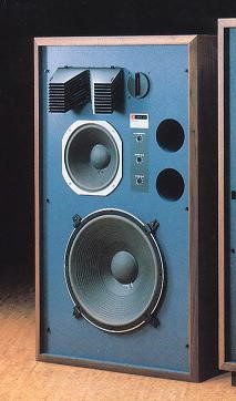
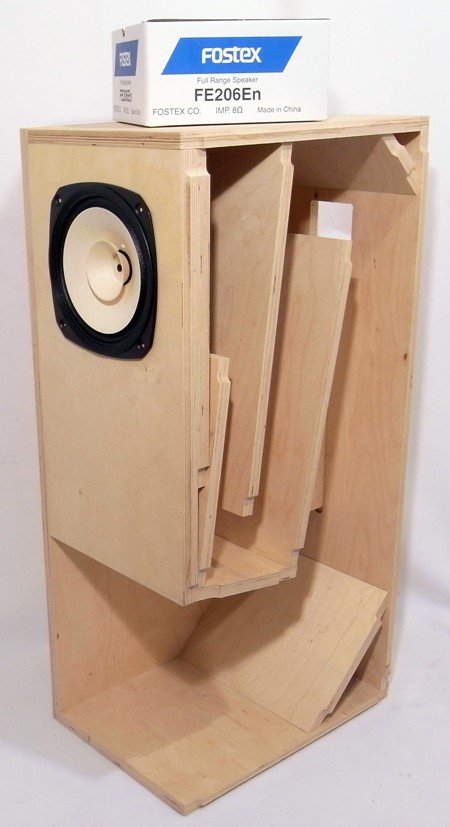
Left: JBL 4344 (1982-1983) Right: Folded horn DIY cabinet with Fostex FE206n[3]
Now, returning to bass speakers, the smaller the speaker, the lesser air it can move. The larger the cone of the speaker will be, the larger the radiating area. Of course there are all sorts of small sized woofers that offer a quite incredible low response for the right (costly) price and outperform larger sized woofers of lower quality. But if we take two bass speakers of same quality and mainly same characteristics, the larger one (the one with the larger cone area) will go deeper in frequency response with a more impressive bass kick.

A bass speaker should also be large to efficiently – as much as possible – impedance match to the air. The specific acoustic impedance of free air is approximately 42 ohms per square cm. For optimum efficiency the radiation resistance of the speaker cone should also be 42 ohms/cm2 , but for sound wavelengths longer than the diameter of the speaker, this impedance drops rapidly . The smaller the speaker, the poorer its low frequency production. That’s one of the reasons why a cone type speaker needs to be complemented by an enclosure. This plus because back-to-front cancellation effect plus to minimize the impact of the resonant frequency of the speakers.
So, just don’t expect that a modest 15-20 liter bookshelf or floorstander loudspeaker will throw you from your sofa. Also, not to be fooled, go to your local shops and listen to several loudspeakers with different bass speaker size. Go and listen live to your local orchestra or your favourite musician. Bass should listen like acoustic bass, not like a variable continuous burp from your loudspeaker or subwoofer. I will not even mention the little portable Bluetooth speakers that can be found everywhere nowadays, impressive as they may scream. Don’t be fooled also by the popular 5.1 or 7.1 systems: they are ment to reproduce recordings with multiple audio channels thus enhancing the perception of sound spacialization by exploiting sound localisation; stacking those satellites together with your subwoofer will not become your audio magnum opus. Yes, adding speakers means more sound pressure, but that’s not the purpose of your surround set.
The proliferation of electronic music genres brought a blow also to acoustic bass and not only. We can’t quite relate to instruments or tell how it should really sound like. That’s just gold for manufacturers of lower quality audio gear. As a side note, I myself listen also to electronic music from time to time and I must say it still does sound better on a proper audio system. Not to mention other genres: with a quality recording of some vocals and instruments, even an untrained ear will be able to tell and feel the difference between a crap system and a proper system.
Closing the circle, we get back to the size: check your living room, consider how much space you’d accommodate for your speakers then go and try several sets. Don’t just buy based on your reads or just because it looks good or impressive. Don’t trust the manufacturer specs also – it’s even worse than the miles per gallon rating for cars from their producers (we’ll get more into that later). And if you can accommodate larger speakers, don’t go for the smaller ones if you want quality. Same for the amplifier, don’t settle for the skinniest. Actually I saw many people buying low powered amplifiers (be them mediocre or good), cranking the volume up one day, ending up with broken speakers and blaming the speakers. Hardly ever you will see a blown speaker because it’s power rating has been exceeded. Especially if the loudspeaker is modern, most likely is innefficient and will drain happily your amplifier without dying. You’ll most likely see an amplifier that was cranked up, reached it’s maximum capacity (be it output voltage or current) and thus had it’s signal clipped and from a nice sine wave the signal became a square-wave waveform, with high frequency harmonics that bring extra overheat to the speaker coils, destroying the coils. Most of the time, you’ll find the tweeters have gone silent or screeching madly.
Going back to buying, you can choose modern, modern-used, vintage or you can go the DIY way – each with pros and cons – for both speakers and amplifiers. We’ll dwell upon many subjects below, but now you know the basics – sturdy amps and large as possible speakers. As I’ve said, a small speaker may easily obliterate a larger speaker if there is a serious quality gap between the two (in favor of the smaller) and also there are small amplifier designs that are surprisingly juicy compared to bigger amplifiers that are actually pretty empty inside. I’ll show you an example below. But without knowing exactly, between A and B, I stick to my rule of thumb, bigger is better. You may very well stop reading – this rule may be sufficient.
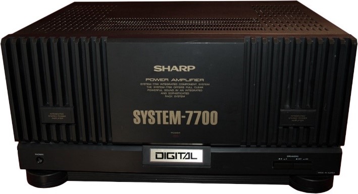
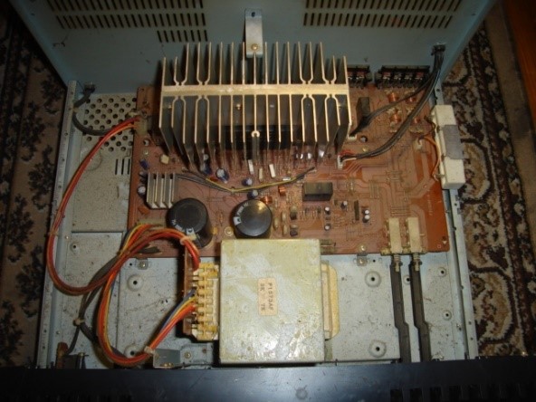
This guy here is approx 16.9 x 8.3 x 13.4 inch. Actually, it’s not a bad amp, but for the purpose of example I chose it. You’d expect here to find a huge toroidal power transformer or several square ones, four Coca-Cola can sized capacitors and some bulky radiators. At this size, you’d probably be entitled to expect some 200 watts into 8 ohms. Actually, this guy is rated somewhere near 120 watts into 8 ohms – not bad at all anyway! Holding it up, I immediately felt something wrong, it weights around 11 kg/24 lb but I expected more for this size and built (you can train also your hands by sligthty weighting these guys every time you have the chance).
You can take a look also to some vintage line of amplifiers from Harman Kardon, the ones with High current/High voltage capability. Not saying they are the best, they are not, but you’ll be shocked to see some skinny amplifier delivering such punches to the speakers, it’s like a Bruce Lee movie. But looking to amps, let’s take a look at the audio signal and speaker impedance.
Music is not an uniform tone signal. There are peaks all over and depending on your song – or why not, movie – the difference between the average and the peaks can go quite high. For the sake of example, let’s consider you were operating your speakers somewhere near 20 watts when there is a loud scream. That can mean easily an instant 50 watt request on your amplifier. Consider this if you were operating your amplifier near it’s edge – it may be unable to deliver the needed power and you’ll get distorsion and clipping. This puts some strain. But the greatest strain does not come from this. One of the biggest problems comes from the speaker impedance, which varies with frequency. This can be best observed by plotting it as a graph, called the impedance curve (see below).

When you look to loudspeakers specifications, you will see “impedance”. Actually, it’s the nominal impedance – a convenient, single number reference that loosely describes the impedance value of the loudspeaker over a majority of the audio band.
The ohm is the unit of measure for impedance, which is the property of a speaker that restricts the flow of electrical current through it (resistance). Some of you may remember Ohm’s law: in an electrical circuit, current flow is directly proportional to voltage and inversely proportional to impedance. Let’s see this in practice:
An amplifier is producing 10 volts AC to an 8 ohm speaker, so the current in the speaker will be 10 volts / 8 ohms or 1.25 amperes. If we connect the same amplifier to an 4 ohm speaker, the lower impedance will allow more current to flow (10 volts / 4 ohms or 2.5 amperes).
Take a look at the graph from above. You are listening to your favourite song on some speakers that have the impedance curve from our graph. You may see that somewhere at 6 kHz (imagine some snares) the impedance is around 8 ohm, while at 100 Hz in your bass area the impedance is about 4 ohms. Using the example with the amplifier producing 10 volts, that means that the current draw is double on the bass area compared to the treble area. There is no speaker on earth (we’re talking about the most common speaker type, the electro-mechanical transducer using a voice coil rigidly connected to a diaphragm) yet with a perfectly flat impedance curve. This stresses out amplifiers and their power supplies.
This can lead to overheating or failure. Wikipedia explains this so well: “Impedance variations of the load with frequency translate into variation in the phase relationship between the amplifier’s voltage and current outputs. For a resistive load, usually (but not always) the voltage across the amplifier’s output devices is maximum when the load current is minimum (and the voltage is minimum across the load) and vice versa, and as a result the power dissipation in those devices is least. But due to the complex and variable nature of the driver/crossover load and its effect on the phase relationship between the voltage and current, the current will not necessarily be at its minimum when the voltage across the output devices is maximum – this results in increased power dissipation in the amplifier output stage which manifests as heating in the output devices. The phase angle varies most near resonance in moving coil loudspeakers. If this point is not taken into consideration during the amplifier design, the amplifier may overheat causing it to shut down, or cause failure of the output devices.”[6]
There’s also a less known characteristic of an amplifier, the damping factor. A serious amplifier should have this among its product specifications. Again Wikipedia says it right: “a loudspeaker acts as a generator when a coil is moving in a magnetic field. When the loudspeaker coil moves in response to a signal from the amplifier, the coil generates a response that resists the amplifier signal and acts as a “brake” to stop the coil movement. This is the so-called back EMF. The braking effect is critical to speaker design, in that designers leverage it to ensure the speaker stops making sound quickly and that the coil is in position to reproduce the next sound. The electrical signal generated by the coil travels back along the speaker cable to the amplifier. Well-designed amplifiers have low output impedance so that this generated signal has little effect on the amplifier.” Amplifier damping factor (DF) is defined as the ratio of the load impedance (loudspeaker plus wire resistance) to the amplifier internal output impedance. It shows the ability of the amplifier to stop the speaker cone from moving and it’s most relevant for the bass drivers where the size and weight of the speaker cone is significant. A system where the damping factor of the entire loudspeaker/wire/amplifier circuit is very low will exhibit poor definition in the low frequency range. Low frequency transients such as kick drum hits will sound “muddy” instead of that crisp “punch” we would ideally want from the system. To jump to a more practical conclusion, a solid state (not vacuum tube) amplifier with a damping factor somewhere over 20 should suffice with any crazy impedance speakers. Exotic manufacturers may boast with damping factors in the hundreds or even more as a secret ingredient. Actually, high or huge damping factors bring nothing more and just look good on paper. What’s more important, damping factor teaches us indirectly that we should keep our speaker cables short as possible and choose larger gauge wires.
Now, because we got a little deeper in the amplifier subject, we’ll stick to that for the moment and attack some other amplifier-related concepts. Common subjects you will often encounter are rated power vs reality, amplifier classes and the vacuum tube vs solid state (endless threads here).
Let’s see first what are the typical amplifier parameters:
- Gain: it is the increase in amplitude of a signal or the radio of the output signal amplitude to the input signal amplitude. It can be calculated for voltage, current, power. You’ll even encounter control knobs labeled as “gain” on microphone preamps or guitar amps.
- Frequency response: amplifiers will not amplify just any signal. Most modern audio amplifiers have a flat frequency response as shown above over the whole audio range of frequencies from 20 Hz to 20 kHz. This range of frequencies, for an audio amplifier is called its Bandwidth
- The input impedance of an amplifier is the effective impedance between the input terminals. “Effective” means that the impedance is not necessarily just that of the amplifier components (resistors, capacitors etc.) actually connected across the input terminals, but is the impedance experienced as the amount of current able to flow into the input terminals for a given signal voltage applied at a particular frequency.
- Phase shift: is the amount (if any) by which the output signal is delayed or advanced in phase with respect to the input signal expressed in degrees.
- Feedback: is the process of taking a proportion of an amplifier´s output signal and feeding it back into the input. Feedback can be arranged to either increase or decrease the input signal. When feedback is used to increase the input signal it is called POSITIVE FEEDBACK, and when the effect of the feedback reduces the input signal it is called NEGATIVE FEEDBACK.
Maybe it’s not so interesting, but chances are we’ll encounter terms like feedback later on. As you can see, I’m jumping from subject to subject. Which can be both bad and good. Actually, I don’t think you’ll find a single material to cover all these subject like I’ve done here. It took me years to be exposed to all this information. Getting back to our topics, let’s head now to amplifier classes first. First of all, we should talk about transistors first. Actually, we won’t, because it’s a huge subject and I’m nowhere near educated myself into the topic and more important, it would be a chapter to big to cover here (an out-of-the box explanation here[7]). Chances are, if you made this far reading, you already know more or less about transistors, semiconductors and vacuum tubes.
Let’s see what are the amplifier classes and what’s the big fuss about them. A, B, AB and C classes refer to the way the amplifiers are biased, while classes D and H are used in switch mode amplifiers where power is saved by having the output transistors switched rapidly between fully on and fully off.[8]
- Class A – Generally desired by a vast majority of audiophiles. Costly. Low output power. High fidelity. Lots of heat. The amplifier is made relatively free from distorsion (by keeping the signal waveform out of the region where the transistor input characteristic is non linear), has good to excellent linearity, but you can expect that output power to be only about 25-30% compared to the DC power they consume. The rest of the wasted power is heat, which will require large heatsinks and space between the components. For example for 100 watts at 8 ohm and the output stage transistors biased at 2.5 A (for +/- 40 V output voltage and peak current +/- 5A), the transistors would need to dissipate 400 watts for just one channel while at idle (no output to the loudspeakers). That’s why you will find expensive low power class A amplifiers on the market or you will find class A only in input stages of amplifiers, in pre-amplifiers or you will find also amplifiers that offer only the first 10-15 watts in class A and what is above in class AB ( ex. Yamaha A-1000, with “auto class A”). Of course some folks created some monsters like the 175.000 USD Audio Power Labs 833TNT (200W at 4 or 8 ohm, using a controlled liquid-cooling system to keep the tubes operating at a safe temperature) or the 2.200.000 USD Pivetta Opera Only that’s made of six 20.000 watt class A amplifier channels with a height of more than 8 feet, 3307 lb weight, featuring six 30 kW triple-insulated toroidal transformers…
- Class B – Much more efficient than class A. Each output transistor only conducts for one half of the signal waveform. They have high distorsion due to gross non-linearities at the point where the two transistors transition from on to off so they are not used in commercial amplifier designs in pure class B form.
- Class AB – Most audio amplifiers would operate in this class. It is a combination of class A and B. The class AB will have higher efficiency than class A but less distorsion that class B. Can be better that class A amplifiers with a bad design. Most of us have or will have a class AB amplifier or have used one. What to say more?
- Class D – They use a different technique in which the output transistors (usually MOSFETs) are rapidly switched on and off at a far higher frequency than the highest audio signal that needs to be reproduced. Because of this design we have low power dissipation (less than class AB) so less heat and also it saves circuit board space and cost. Disadvantages include the need for expensive output filters, some degree of radiation/interference from the amplifier that occurs and must be tamed etc. Historically, their sound quality is not so good as a decent class AB amplifier but in the last ten years the class D technology has been refined more and more so the gap is narrowing, with many people not finding any audible difference between classes AB and D. On the market, you’ll find class D mostly used for subwoofer amplification, car audio amplifiers but also for power audio applications. And more and more home amplifiers.
- Class C – Ok, let’s mention it. Heavy distorsion, so not used for audio amplifiers but for other stuff.
- Classed G & H – Improved efficiency over class A/B, costlier than class A/B but higher levels are achievable in a smaller form factor. Class G uses multiple power supply rails of various voltages, rapidly switching to a higher voltage when the audio signal wave has a peak value that is a higher voltage than the level of supply voltage, and switching back to a lower supply voltage when the peak value of the audio signal reduces. By switching the supply voltage to a higher level only when the largest output signals are present and then switching back to a lower level, average power consumption, and therefore heat caused by wasted power is reduced. Class H improves on class G by continually varying the supply voltage at any time where the audio signal exceeds a particular threshold level. The power supply voltage tracks the peak level of the signal to be only slightly higher than the instantaneous value of the audio wave, returning to its lower level once the signal peak value falls below the threshold level again. Both classes G and H therefore require considerably more complex power supplies, which adds to the cost of implementing these features. You’ll find them mostly in designs for power audio.
Actually, what should we remember from all this? We should remember that theoretically: class A has the least amount of distorsion but with least efficiency at a high cost and low power output (so a compromise is to use it in preamplifiers or in input stages inside the amps) compared to other classes; class AB is the most commonly used design bringing power at low distorsion; class D is more used in car audio and subwoofer amplification but catches on class AB on sound quality with lower heat dissipation related costs while classes G&H are used in power audio designs due to the power to size ratio they can achieve but also are more costly. Also we should remember that efficiency is a key factor for all classes and thus the power consumed by an amplifier (what we see written on the back of the chassis which can be also the average value or the maximum) can be many times larger that the actual maximum power delivered to your speakers.
Let’s head to vacuum tube amplifiers or tube amplifiers. The simplest valve was invented by John Ambrose Fleming but the first electronic amplifying device, the triode, was invented by Lee Dee Forest. The first amplifiers were operating in class A with a single-ended triode gain stage. Technology regarding the vacuum tubes and so for the amplifiers using tubes evolved but during the 1970s the transistor became increasingly pervasive so the vacuum tubes production decreased. Vacuum tubes generally provided low gain but with a high linearity making them good for use in low distorsion liner circuits with little or no negative feedback and thus no phase shift issues. They also operate at higher voltages and lower currents than transistors, can withstand very high transient peak voltages but also require a cathode heater, are significantly larger than transistors and have a shorter working life than solid state parts due to various failures (from heat, cathode poisoning, breakage, internal short-circuits etc.). Also because of their high output impedance (compared to transistors), valves usually require matching transformers to drive low impedance loads such as loudspeakers which brings an extra high cost.
Besides some specific applications where tubes are still used, we’ve seen a dramatic comeback in the last ten years in the vacuum tube amplifier market. Many feel that tubes are sonically superior technology for audio. Some of the reasons cited are valves allow for generally simpler circuits, are more tolerant of deviations in component specification and most important, the onset of clipping as maximum power is reached is gradual and rising distorsion is of predominately low even-order harmonic nature. Many describe the vacuum tube amplifier sound as warm, rich and more pleasant to the ear. Actually, scientific tests were made and the perceptions were confirmed: an overdriven valve amp produces strong even harmonics which add a sweetening, warm complexity to a sound while an overdriven transistor amplifier creates strong odd harmonics which can cause dissonance. When transistors overload, the dominant distortion product is the third harmonic. The third harmonic produces a sound many musicians refer to as blanketed with a tone perceived as thin and hard. On the other hand, with tubes (particularly triodes) the dominant distortion products are the 2nd-order harmonics (that are at double the fundamental frequency, one octave higher) and they add body to the sound, making it more musical. We can say tubes sound better because mainly because their distortion products are more musical.
Tube guitar amplifier manufacturers have traditionally designed their circuits to drive the output stages into overload distortion, using the resultant distortion to achieve their trademark “tone”. In a tube amplifier, this tone contributes to the amplifier’s sound.

Moving into power ratings, first of all we should never use the amplifier at maximum level for so many reasons. Secondary, we should also remember always that the output level of the amplifier is dependant on the input signal level. More than that, an amplifier is able to produce a higher power than specified by the producer but with a greater level of distorsion and with risks. We don’t want that. It’s important also the load impedance of the amplifier – generally you’ll see it something like 4-16 ohms or 8-16 ohms for main or remote and 8 ohm – 16 ohms for main and remote. Is your amplifier stated only for 8 ohms load impedance? No problem, you can use also 4 ohm speakers, just keep in mind not the pass 30% of the maximum power.
For the amplifier power, we will be interested in the effective output into either 8 or 4 ohm on the full frequency range (not actually full, but from 20 Hz to 20 kHz) at it’s lowest THD (Total Harmonic Distorsion). I’m not interested if this amplifier can reach 2x220W on 1 kHz only – I’m interested it outputs actually 2x150W between 20 Hz and 20 kHz. I’m not interested also what’s the power output at 0,02% THD or 0,1% THD…. I’m interested at the output power at it’s minimum stated THD, which could be 0,003%. Actually, having high sensitivity speakers, you may not care about amplifier power output. 10 watts could be all you need.
But how loud can one amplifier be compared to another? Let’s compare one 100W amplifier to one 50W amplifier. The 100W amplifier would be only 3 dB louder than the 50W one. When it comes to loudness, a 10 dB increase is roughly the equivalent of doubling of perceived loudness. The decibels are a logarithmic unit of measurement. Four times the power would mean an increase of 6 dB. Ten times the power would mean an increase of 10 dB. So, roughly, a 500W amplifier would be considered to be twice as loud as a 50W one. A bit shocking if you hear it for the first time, right? While 1 dB change is hard to be heard, 3 dB would be smallest difference in level that is easily heard by most listeners listening to speech or music. Your amplifier volume potentiometer is also logarithmic.
Let’s correlate this now with speaker sensitivity. Speaker sensitivity is measured in a non-reflective, soundproof room called an anechoic chamber. Let’s take an example with a speaker that has the sensitivity of 90 db @ 1W/1m, meaning 90 decibels SPL level with one watt of power, measured at a distance of one meter from the speaker. So when this speaker is powered with 1 watt, it will generate 90 dB or 93 dB if powered with 2 watts or at 10 watts I will generate 100 dB power at 1 meter, that is twice the perceived loudness when compared to 1W. At one 100W, these speakers would reach 110 dB.
Now let’s take some high sensitivity speakers with 100 dB @ 1W/1m. At 1W input these speakers will generate 100 dB measured at 1 meter. Or 103 dB at 2W. Or 110 dB at 10W. So we could say that the first speakers at 90 dB and 100W sound as loud as the second 100 dB speakers at 10W. Old vacuum tube and transistor amplifiers had low power output but that was not a problem because many vintage speakers were of high sensitivity. For that, they were built lightweight, which was also a happy thing for their magnets who were able to quickly accelerate their cones – so no need for huge magnets plus other benefits.
You’ve also probably heard about RMS power. Actually the correct term is continuous average power and it’s the maximum amount of power an electronic component can possibly handle continuously without damage. In US, to combat the unrealistic power claims made by many hi-fi amplifier manufacturers, the Federal Trade Commission prescribed continuous power measurements performed with sine wave signals on advertising and specification citations for amplifiers sold in the US. Typically, an amplifier’s power specifications are calculated by measuring its RMS output voltage, with a continuous sine wave signal, at the onset of clipping. You can find more info by reading the law act – the 1974 Amplifier Rule. Of course there are other standards also in other areas of the world (ex DIN specifications from the Deutsches Institut für Normung).
You’ve probably heard also of PMPO while buying some computer speakers or some boombox. The term PMPO will appear along with gargantuan wattage figures with many zeros. There’s no standard for PMPO. It’s just used to catch the attention of an average consumer. I will not explain more, just ignore this rating.
The continuous rating is the base line wattage that the cabinet can handle without risking any harm to the voice coil or other parts of the speaker.
The program rating is the maximum wattage that the speaker can handle in bursts. This is usually the better amplifier wattage to shoot for when matching an amp to a speaker.
The peak rating is the maximum wattage the voice coils can take in very short peaks. As mentioned before, this is used if you are trying to achieve the maximum output of the speaker.
Regarding speakers, we now know about the relation between the bass speaker cone area and the quantity of air that it can move. We talked about why a cone type speaker would need to be complemented by an enclosure. We know now also that a low power amplifier can damage your speakers if you turn the volume too much. We know also the speaker impedance varies with frequency. And we’ve given some examples of perceived loudness with amplifiers at different output powers and speakers with different sensitivities. We also talked about speaker power ratings and we know speaker sensitivity is or let’s say it may be more important than speaker (supported) power.
We can dive more into speakers now.
The loudspeaker involves electromechanical processes where the amplified audio signal must move a cone or other mechanical device to produce sound like the original sound wave. This process involves many difficulties, and usually is the most imperfect of the steps in sound reproduction. For the most common used speakers, a light voice coil is mounted so that it can move freely inside the magnetic field of a strong permanent magnet. The speaker cone is attached to the voice coil and attached with a flexible mounting to the outer ring of the speaker support.
Loudspeaker enclosures TYPICALLY involve multiple loudspeakers with a crossover network to provide a more nearly uniform frequency response across the audio frequency range. Regarding their type, speakers could generally be tweeters, mid-tweeters, midranges, midwoofers, subwoofers. Depending on their designed purpose, some tweeters may cover well the midrage area also or some woofers may also go up into the midrange area. That’s how we have the 2-way speakers that we often see, especially in bookshelf speakers. It depends how well the speaker covers the intended frequency range. If you just take a random tweeter and a woofer and match them with a crossover network most probably you will get a “hole” in the midrange area. And it’s more than that. To built a loudspeaker, the speakers must be matched in many ways. Even if they have similar characteristics or complement each other very well, there is no such thing as perfection. To make them work as a team and create a coherent sound image we need to use a crossover, which can be active or passive (electronic filter). The crossover directs the bandwidth of frequencies each driver is optimized to reproduce while it also level matches each driver and can help to stabilize the load impedance the amplifier will see. Even the basic designs would need a capacitor for the tweeter so the unwanted bass frequencies do not enter the tweeter and damage it. A typical (3-way) loudspeaker would have a tweeter, midrange and a woofer and would use a 3-way crossover – constructed as a combination of low-pass, band-pass and high-pass filters. There are different types of crossovers with different filter slopes: first order, second order (with either Bessel, Linkwitz-Riley or Butterworth characteristic), third order and fourth order. It all depends on the loudspeaker design choice and components used. Like it or not, the crossover is one of the most important components of a loudspeaker and with a bad design, it can make a loudspeaker with superb expensive speakers sound awful. Actually, during development phase of a loudspeaker, after the speakers have been mounted in an enclosure and tests are being made, producers do a fine tuning of the crossovers, changing crossover components so they obtain the sound or characteristic they aimed for.
“A good sounding loudspeaker needs to have smooth and flat on-axis frequency response and similar performance as we move far off axis. We describe this in terms of directivity as a function of frequency, and although absolutely constant directivity is not necessary, smooth and gradually-changing directivity is a good objective. In deciding on the drivers to be used in a speaker system it is necessary to ensure that at crossover frequencies the drivers have closely matching directivities. This means that when the acoustic transition is made between, say, a woofer and a midrange, or a midrange and a tweeter, there is continuity in the directional sound radiation pattern. It is not sufficient just to have a good looking on-axis response. So, in addition to selecting drivers for their usable bandwidths and power handling capabilities, we need to pay attention to their directional radiation patterns. The most difficult transitions occur when the transducers involved are very different in size.”[10]
An exception to not having a crossover would be the single driver full-range drive loudspeakers. These fullrange speakers reproduce as much of the audible range as possible within the limitations imposed by the physical constraints. Here a crossover network is not a must and generally, not recommended. Critics of full range drivers cite their inability to reproduce the full range of audio frequencies at similar amplitudes, leading to inaccurate reproduction of the audio signal sent to it. If the driver is small we will get weak or no bass at all, while if the size is big its treble will be limited. Solution would come from midsized – 5, 6 inches – fullrange drivers mounted in large transmission lines or horn loaded enclosures – thus being able to output both decent bass and treble. Fullrange loudspeaker fans claim superior phase coherence and thus a better sound coming from only one speaker. Small radios or stereos and tv usually use fullrange speakers.

I feel compelled to cite an expert:
“If size is not a limiting factor, we can get really low bass and very high efficiency. If size is restricted, we have to sacrifice efficiency – or low-end extension. If you want high efficiency – and small volume – you have to sacrifice deep bass. Etc. The thing is – we can’t have it all. You have to pick your priorities.”[12]
Going to speaker materials, there are so many nowadays: paper, aluminum, carbon, bamboo, aerogel, glass fiber, kevlar, polypropylene, polymers etc. Each material comes with pluses and minuses. In the end, it mostly depends on the craftsmanship of the manufacturer for the intended product (and cost, of course).
While the dynamic cone speakers remain the most popular choice, many other speaker technologies exist: moving-iron speakers (the first type invented), piezoelectric, magnetostatic, magnetostrictive, electrostatic, ribbon, planar etc. There’s a rising usage in ribbon tweeters used nowadays; they offer very good high-frequency response but are quite fragile and costly. Electrostatic speakers have lots of fans because of their great linearity and low distorsion compared to dynamic siblings (they need to be used in combination with a conventional subwoofer speaker to handle bass frequencies effectively) but they are costly and very large.
“Early on, radio loudspeakers consisted of horns, often sold separately from the radio itself, (typically a small wood box containing the radio’s electronic circuits), so they were not usually housed in an enclosure. When paper cone loudspeaker drivers were introduced in the mid 1920s, radio cabinets began to be made larger to enclose both the electronics and the loudspeaker. These cabinets were made largely for the sake of appearance, with the loudspeaker simply mounted behind a round hole in the cabinet. It was observed that the enclosure had a strong effect on the bass response of the speaker.[…]
In some respects, the ideal mounting for a low-frequency loudspeaker driver would be a rigid flat panel of infinite size with infinite space behind it. This would entirely prevent the rear sound waves from interfering (i.e., comb filter cancellations) with the sound waves from the front. An open baffle loudspeaker is an approximation of this, since the driver is mounted on a panel, with dimensions comparable to the lowest wavelength to be reproduced. In either case, the driver would need a relatively stiff suspension to provide the restoring force which might have been provided at low frequencies by a smaller sealed or ported enclosure, so few drivers are suitable for this kind of mounting.
The forward- and rearward-generated sounds of a speaker driver appear out of phase from each other because they are generated through opposite motion of the diaphragm and because they travel different paths before converging at the listener’s position. A speaker driver mounted on a finite baffle will display a physical phenomenon known as interference which can result in a perceivable frequency-dependent sound attenuation. This phenomenon is particularly noticeable at low frequencies where the wavelengths are large enough that interference will affect the entire listening area.
Since infinite baffles are impractical and finite baffles tend to suffer poor response as wavelengths approach the dimensions of the baffle (i.e. at lower frequencies), most loudspeaker cabinets use some sort of structure (usually a box) to contain the out of phase sound energy. The box is typically made of wood, wood composite, or more recently plastic, for reasons of ease of construction and appearance. Stone, concrete, plaster, and even building structures have also been used.
Enclosures can have a significant effect beyond what was intended, with panel resonances, diffraction from cabinet edges and standing wave energy from internal reflection/reinforcement modes being among the possible problems. Bothersome resonances can be reduced by increasing enclosure mass or rigidity, by increasing the damping of enclosure walls or wall/surface treatment combinations, by adding stiff cross bracing, or by adding internal absorption. […]
The designer must balance low bass extension, linear frequency response, efficiency, distortion, loudness and enclosure size, while simultaneously addressing issues higher in the audible frequency range such as diffraction from enclosure edges, the baffle step effect when wavelengths approach enclosure dimensions, crossovers, and driver blending.”[13]
I want to list some of the speaker manufacturers on the market: Audax, Dayton, Eton, Focal, Fostex, Fountek, Hi-Vi, Manger, Morel, Markaudio, Morel, Peerless, SB Acoustics, Scanspeak, Seas, Supravox, Tang Band, Usher, Vifa (of course the list is just partial). Some of them, like Usher, make (great) loudspeakers also while some just supply for other companies and/or DIY projects. While for some these are acclaimed brands, many never heard of them. What many people know is Harman International products, Bose, Sennheiser, Dynaudio, Bowers & Wilkins, Bang & Olufsen, Yamaha etc. For many people a Bose system would be the supreme audio system. Going into the homes of audio fanatics you will generally not find such brands – many will go for brands like: Audio Physic, Bowers&Wilkins, Dali, Elac, Epos, Focal, KEF, Klipsch, Wharfedale, Tannoy, Martin Logan, Mourdaunt Short, Naim, Triangle, Sonus Faber, ProAc, Paradigm, Manger etc. while others will go for more esoteric brands and products.
Power audio professionals will relate more to loudspeaker brands like Dynacord, JBL, Peavey, QSC, RCF, Yamaha, Electrovoice, Mackie, Meyer Sound etc. while in studios we may see other brands like Adam, Focal, Genelec, ESI, Fostex, KRK, Presonus, Tannoy, Tascam, Dynaudio. For musicians we come into another league with Marshall, Fender, Roland, Peavey, Bugera, Orange etc.
Some manufacturers will be found both in home audio and automotive (ex Bose, Harman Kardon, Cabasse, Dynaudio), some like Yamaha will have products everywhere – home, power audio, musicians, studios etc, while others will target only a specific niche in the market.
Whatever audio product tomorrow may bring, you now have better insights into the subject. Although we did not speak about audio sources, cables, audio formats, room acoustics and many other subjects, I think we laid down an interesting foundation to begin with.
I hope this little guide will come in handy for many of you. If you found something inaccurate, please let me know so I can correct it. If you liked it, let me know also.
Marius
[1] Source: https://guarantymedia.com/95-of-u-s-households-have-at-least-one-broadcast-radio-receiver/
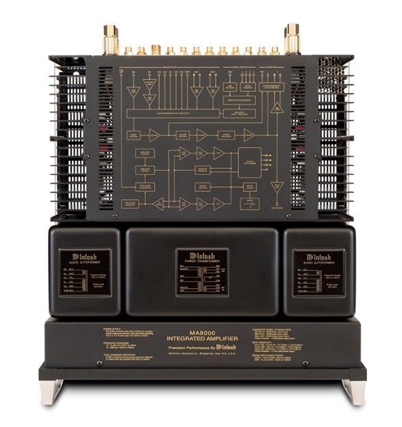
[2] Macintosh MA8000 amplifier
[3] Source: https://www.madisoundspeakerstore.com/full-range-speaker-kits/fostex-bk-20-folded-horn-kit-pair/
[4] Source: http://www.sengpielaudio.com/calculator-wavelength.htm
[5] Source: http://www-etud.iro.umontreal.ca/~boulanni/amt.png, author Nicolas Boulanger-Lewandowski
[6] https://en.wikipedia.org/wiki/Electrical_characteristics_of_dynamic_loudspeakers
[7] http://amasci.com/amateur/transis.html
[8] Many electronic devices such as diodes, transistors and vacuum tubes, whose function is processing time-varying (AC) signals also require a steady (DC) current or voltage to operate correctly — a bias. The AC signal applied to them is superposed on this DC bias current or voltage. The operating point of a device, also known as bias point, quiescent point, or Q-point, is the DC voltage or current at a specified terminal of an active device (a transistor or vacuum tube) with no input signal applied. A bias circuit is a portion of the device’s circuit which supplies this steady current or voltage.
[9] Source: http://www.mcintoshlabs.com
[10] Editorial Note About Directivity, Crossover Points & Driver Selection by Dr. Floyd Toole
[11] https://www.passdiy.com/projects/images/content/kleinhorn1.png, Nelson Pass, Kleinhorn design
